Front Support Beam
Step 1: Add Screws to Corner Brackets
Parts Needed:
REV-41-1320 – Bracket, Inside Corner (2)
REV-41-1359 – Screw, Hex Cap, M3, 8mm (8)
REV-41-1361 – Nut, Locking, M3 (8)
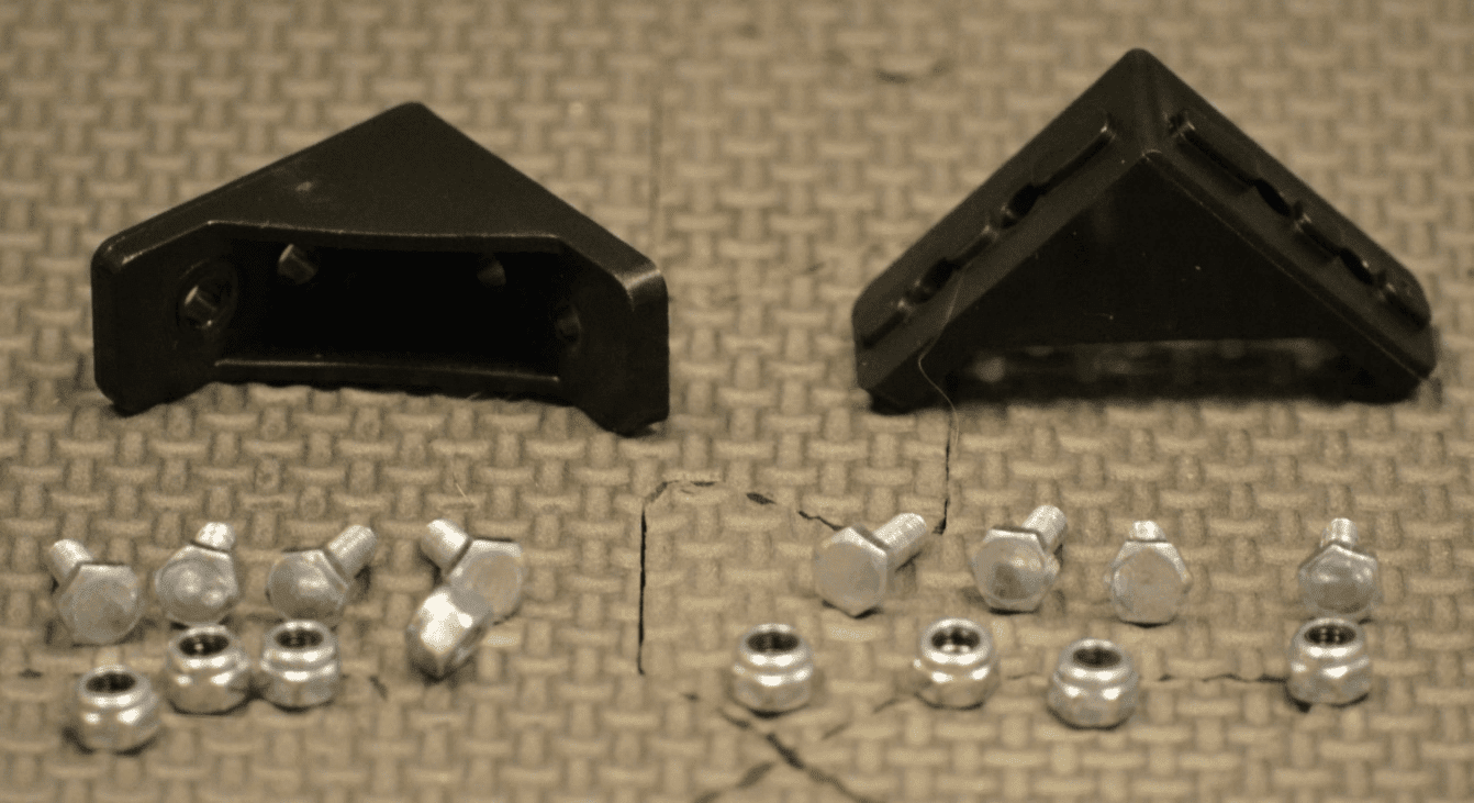
Figure 18- Unassembled view
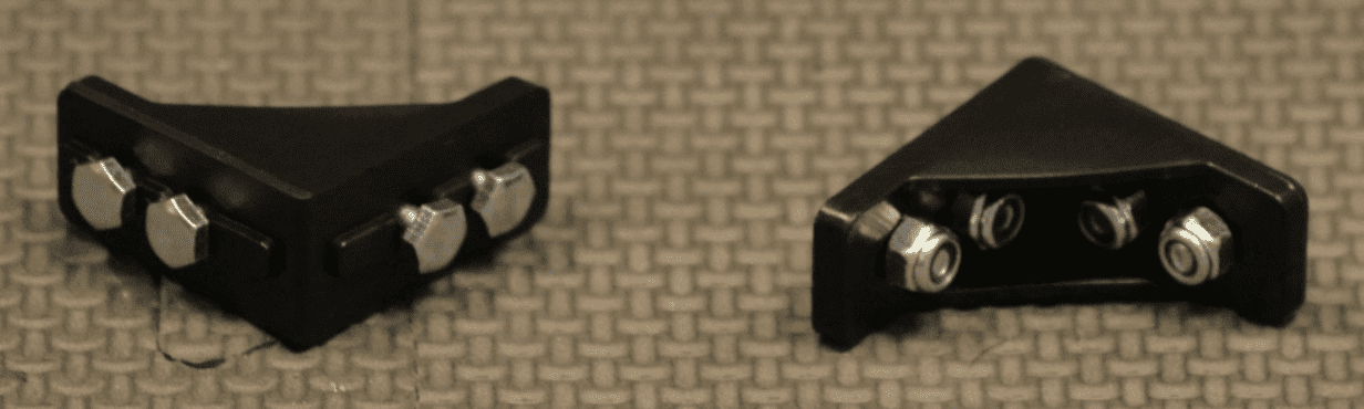
Figure 19- Assembled view
Hint
Screw the nuts onto the screws just until it’s difficult to turn them; just so that the nuts don’t fall off. The screw heads will need to slide along the center of an extrusion in a later step.
Step 2: Add Corner Brackets to Beam
Parts Needed:
REV-41-1431 – Extrusion, 225mm, 90-90 Degree (1)
Corner Bracket Assemblies (2 - from step 1)
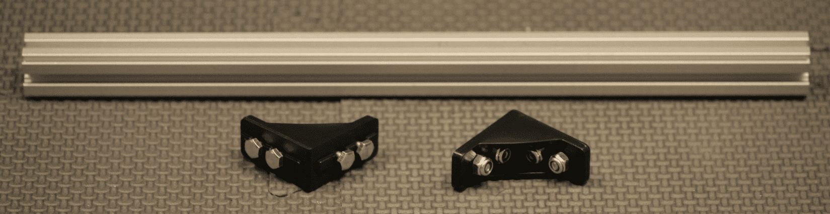
Figure 20- Unassembled view
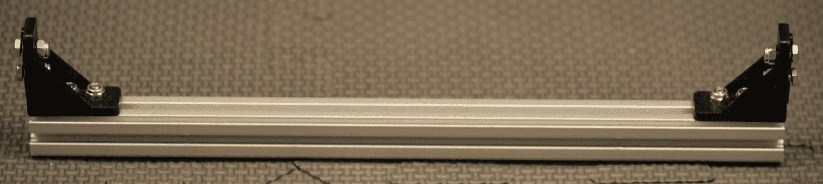
Figure 21- Assembled view
Step 3: Add Floating Screws to Beam
Parts Needed:
Front Beam Assembly (1 - from step 2)
REV-41-1359 – Screw, Hex Cap, M3, 8mm (2)
REV-41-1360 – Screw, Hex Cap, M3, 16mm (2)
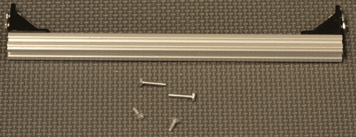
Figure 22- Unassembled view
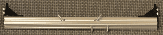
Figure 23- Assembled view
Hint
Two of the 8mm screws are loaded onto what will become the front face of the beam.
One of the 8mm and two of the 16mm screws are loaded onto what will become the top face of the beam
Step 4: Add Front Support Beam
Parts Needed:
Chassis (from Back Support Beam, step 4)
Front Support beam assembly (1 - from step 3)
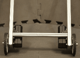
Figure 24- Unassembled view
Figure 25- Unassembled view
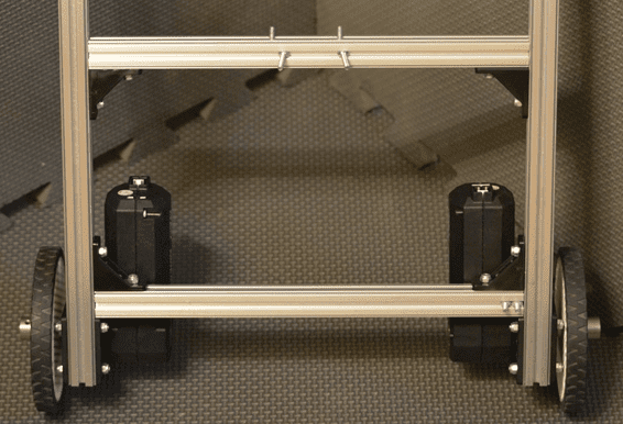
Figure 26- Assembled view
Hint
There should be 121mm between the back support beam and the front support beam (there will be 136mm center to center).
If a ruler is not available, the position may need to be adjusted in a later step.
Step 5: Add Switch Bracket
Parts Needed:
Chassis Switch Plate (part of REV-31-1387)
REV-41-1361 – Nut, Locking, M3 (2)
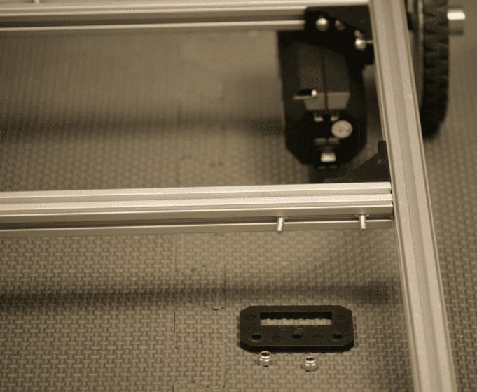
Figure 27- Unassembled view
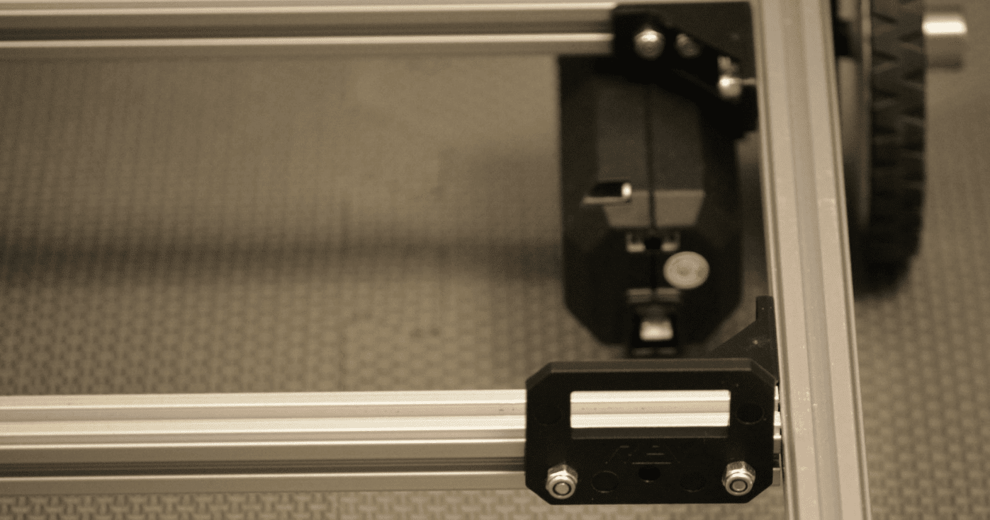
Figure 28- Assembled view